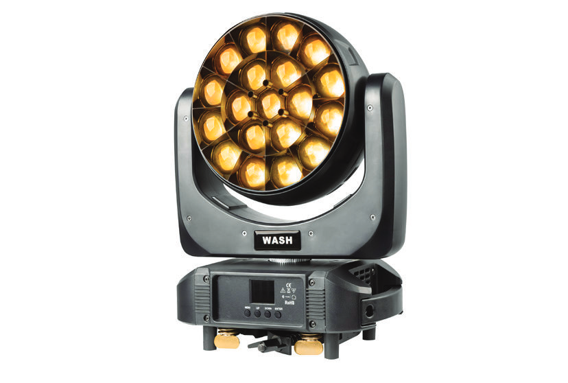
Model LU1920Edition EN · 09 / 2026 · V1 Document No. LU1920-EN-01
LED Beam Moving Head · Pixel Control
LU1920
19 × 20 W RGBW beam with motorised zoom 5.8° – 55°, lens rotation and pixel mapping
Operating manual. Please read in full before first use and keep for future reference.
Light source
19 × 20 WRGBW 4-in-1 LED
Zoom
5.8° – 55°motorised linear
DMX
21 – 997 channel modes
Pan / tilt
540° / 270°16-bit resolution
Luminus LU1920Foreword · About this document
Foreword
00Welcome
Thank you for choosing the Luminus LU1920 — a powerful LED beam moving head with 19 RGBW LEDs, motorised zoom, lens rotation and full individual LED control (pixel mapping).
This document describes set-up, operation, care and troubleshooting of the fixture. Read the manual — in particular the chapter Safety Instructions — in full before first use and keep it with the fixture. If the fixture is passed on to third parties, the manual must be included.
0.1Symbols used
WarningMarks situations in which persons may be injured or the fixture may be damaged. Always observe these instructions.
NoteMarks useful additional information, tips or explanations that aid understanding.
Danger — voltageMarks situations involving danger to life from electric current. Work on live parts is reserved for qualified personnel only.
0.2Intended use
The LU1920 is a professional lighting fixture for indoor use on stages, in discotheques, in television and film studios and at events. Any other use — in particular outdoors or in humid environments (IP20) — is considered improper and voids the warranty.
0.3Package contents
1 × Luminus LU1920 LED beam moving head
2 × Omega bracket with quick-lock
1 × PowerCon power cable · 1 × Safety cable
1 × Operating manual
Luminus LU1920Contents · Overview
Table of Contents
—Overview
01Safety Instructions04
1.1General safety04
1.2Installation and rigging05
02Technical Specifications06
03Set-up07
3.1Step-by-step set-up07
3.2DMX cabling & power linking08
04Menu Map09
05DMX Channels10
5.1Mode overview & effect reference10
5.221-channel mode11
5.323-channel mode12
5.435-channel mode & pixel modes (78 – 99 CH)13
06Troubleshooting14
07Cleaning & Maintenance15
—CE Declaration of Conformity15
Luminus LU192001 · Safety Instructions
Chapter 01
01Safety Instructions
Read this chapter in full before first use. Damage caused by disregarding these instructions is excluded from the warranty.
1.1General safety
Danger to life from electric currentDo not touch any live wires during operation. Open the fixture only at least 5 minutes after switching off and after disconnecting the mains supply. Before connecting, make sure that voltage and frequency match the rating label (AC 100 – 240 V, 50 / 60 Hz).
The protective earth conductor (yellow / green) must be properly earthed to avoid electric shock.
The fixture is intended for indoor use only — IP20. Never expose it to rain, splash water or high humidity.
Ensure adequate ventilation — at least 50 cm from adjacent surfaces; do not cover any ventilation slots.
Keep flammable materials (curtains, decoration) at least 1.2 m away from the fixture — fire hazard.
Disconnect the fixture from the mains before any service or maintenance work.
Always use a safety cable when rigging. Never carry the fixture by the head — always by the base.
Replace damaged housings or lenses before further use. There are no user-serviceable parts inside — repairs by authorised personnel only.
Never look directly into the LED source while the fixture is switched on.
In the event of serious operating problems, stop using the fixture immediately and contact service.
High surface temperatureThe housing temperature can reach up to 85 °C during operation. Do not touch the housing bare-handed during operation. After switching off, allow the fixture to cool for at least 15 minutes before handling. Maximum ambient temperature Ta = 45 °C; permissible range −25 °C to +45 °C.
Luminus LU192001 · Safety Instructions
1.2Installation and rigging
The LU1920 is mounted to a truss or stand via the screw holes in the base using the supplied Omega brackets. Installation must be carried out by qualified personnel. The LU1920 can be operated in three positions: hanging (head down) from a ceiling, sideways on the truss or standing on a level surface.
Risk of fallingThe supporting structure must be able to hold at least 10 times the fixture weight without deformation. Additionally secure the fixture with a safety cable rated for at least 12 times the fixture weight. Never stand directly under the fixture during installation, removal or servicing.
Overhead rigging requires extensive experience — including load calculation, suitable installation material and regular safety inspection of material and fixture.
Fix the fixture so that it cannot vibrate or slip during operation.
Use only the dedicated eyelets on the base for the safety cable — never the carrying handles.
The installation must be inspected by a competent person at least once a year.
Mounting with Omega brackets
Fit the clampBolt one clamp with M12 bolt and nut to each Omega bracket.
Insert the Omega bracketsInsert the quick-locks of the Omega brackets into the openings in the base and turn them fully clockwise to lock. Fit the second bracket in the same way.
Hang the fixtureHang the fixture on the truss via the clamps and tighten the bolts.
Secure the safety cableRoute the safety cable through the opening in the base plate and over the truss; insert and tighten the locking screw.
Luminus LU192002 · Technical Specifications
Chapter 02
02Technical Specifications
Light source & optics
Light source
19 × 20 W RGBW 4-in-1 LED
Power consumption
350 W
Beam angle
5.8° – 55°
Zoom
motorised linear
Lens rotation
CW / CCW, continuous
Dimmer
0 – 100 % continuous, 4 curves
Strobe
1 – 25 Hz, variable
Movement
Pan
540° / 360° selectable
Tilt
270°
Resolution
8 / 16 bit
Power supply
Voltage
AC 100 – 240 V (auto-sensing)
Frequency
50 / 60 Hz
Connector
PowerCon IN / OUT
Control
Protocol
DMX-512 / RDM
Channel modes
21 / 23 / 35 / 78 / 92 / 97 / 99
Operating modes
DMX · Master / Slave · Auto · Sound
Data connection
3- & 5-pin XLR IN / OUT
Display
1.8″ TFT colour display, 180° rotatable
Mechanical
Dimensions (W × D × H)
254 × 338 × 375 mm
Net weight
8.5 kg
IP rating
IP20 (indoor only)
Ambient temperature
−25 – 45 °C
Packaging
Carton (1 unit)
10 kg
Flight case 4-in-1
760 × 575 × 600 mm · 73 kg
2.1Features
Pixel control: each of the 19 LEDs can be addressed individually — display arrows, numbers, letters and patterns.
Highly efficient optical system with flower effect and zoom.
Temperature-controlled fan speed (Auto / Low / High); LED temperature protection adjusts fan speed automatically to the head temperature.
Automatic voltage detectionThe LU1920 has an automatic voltage switch and detects the applied mains voltage by itself — the fixture can be operated worldwide without manual switching.
Luminus LU192003 · Set-up
Chapter 03
03Set-up
3.1Overview & control buttons
LED head19 × 20 W RGBW with zoom & lens rotation
YokeCarries the head, integrates the tilt drive
TFT display & buttons1.8″ colour display with 5 control buttons
DMX IN / OUT3- & 5-pin XLR, data can be linked through
PowerCon IN / OUTLocking mains connection, can be linked through
Fuse & switchFixture fuse next to PowerCon IN, ON / OFF
Button
Function
MENU
Select programming functions
UP
Forward in the selection
DISPLAY
Show menus and the selected function
DOWN
Backward in the selection
ENTER
Confirm / save the selection
3.2Step by step
Unpack and inspectCarefully remove the fixture from the packaging and check for transport damage. Keep the packaging for transport or return shipment.
Choose the mounting locationWell-ventilated location with at least 50 cm clearance on all sides and 1.2 m from flammable materials. Supporting structure: 10 times the fixture weight.
Fit the Omega bracketsInsert both Omega brackets with the quick-locks into the base and turn them fully clockwise (see 1.2).
Attach the safety cableRoute the safety cable (min. 12 times the fixture weight) through the opening in the base plate and over an independent anchor point.
Connect the DMX cableConnect the DMX output of your controller to DMX IN (3- or 5-pin); link through to the next fixture via DMX OUT (see 3.3).
Connect the power cablePlug in and lock the PowerCon cable. Can be linked through via Power OUT — max. 3 fixtures at 120 V, max. 7 fixtures at 240 V.
Set channel mode & DMX addressSelect the channel mode in the “Channel” menu and set the start address via “Address” (see chapter 4).
Wait for the resetAfter power-on the fixture performs a reset. Wait until the head is in its home position before controlling it.
Luminus LU192003 · Set-up
3.3DMX cabling
The LU1920 is controlled via DMX-512. Controller and fixture require a 3- or 5-pin XLR connection for data input and output. Use only shielded DMX cables with 110 – 120 Ω impedance — no microphone cables.
DMX controller OUT ──► LU1920 addr. 001 (IN ► OUT) ──► LU1920 addr. 022 ──► LU1920 addr. 043 ──► 120 Ω TERM.
First fixture: address 1 · next fixture: address + channel count of the selected mode (e.g. +21) · last fixture: 120 Ω terminator on DMX OUT
XLR pinout
Pin 1
Shield / GND
Pin 2
Data − (DATA −)
Pin 3
Data + (DATA +)
Pin 4 / 5
not used (5-pin)
Do not connect the shield to the ground lug — risk of short circuit.
Address calculation (example 21 CH)
Fixture
Address
Channels used
Fixture 1
001
001 – 021
Fixture 2
022
022 – 042
Fixture 3
043
043 – 063
3.4Power linking & master / slave
Several fixtures can be linked through via the PowerCon IN / OUT sockets. Without an external controller, slave fixtures follow a master that plays an auto or sound program (“Mode” menu).
Maximum fixtures per circuitAt 120 V a maximum of 3 fixtures, at 240 V a maximum of 7 fixtures may be linked through. Once this number is reached, use a new circuit. Note that the power consumption of other fixtures in the chain may vary.
Luminus LU192004 · Menu Map
Chapter 04
04Menu Map
The 1.8″ TFT colour display on the base shows the current menu level. Five buttons are used for navigation; the display can be rotated by 180° (“Reverse → Display” menu).
Setting the DMX address
Navigate to “Address” with MENU and confirm with ENTER.
The display shows “DMX Address: 001”. Change the value with UP / DOWN.
Save and exit with ENTER — exit without saving with MENU.
NoteThe “Adjust” sub-menu is password protected to prevent accidental changes to the fine calibration.
Manual control (Focus = zoom, Rota = lens rotation)
4
Pan Degree
540° · 360°
Pan range limit
5
Reverse
Pan · Tilt · Display — Yes / No
Reverse direction / display
6
Mic Sense
001 – 100
Microphone sensitivity (sound)
7
Language
English · Chinese
Menu language
8
No Signal
Black Out · Hold
Behaviour on DMX loss
9
Fan Set
Auto · Low · High
Fan mode
10
Reset
Yes · No
Trigger reset
11
Default
Yes · No
Restore factory settings
12
Information
CH Value · Temp °C · Soft V.xxx
Channel values, LED board temperature, software version
13
Adjust (password)
Pan, Tilt, Focus, Rota, R, G, B, W — 0 – 255
Fine calibration
Luminus LU192005 · DMX Channels
Chapter 05
05DMX Channels
5.1Mode overview
The LU1920 offers seven DMX channel modes. The compact modes (21 / 23 / 35 CH) control all LEDs together; the pixel modes (78 – 99 CH) address each of the 19 LEDs individually.
Movement first, plus static / dynamic patterns and back colour
35
Extended
Full pattern effect block with foreground / background strobe
78
Pixel RGB
21-CH base + 19 × RGB individually (pixel mapping)
92
Pixel RGB +
35-CH base + 19 × RGB individually
97 / 99
Pixel RGBW
21- or 23-CH base + 19 × RGBW individually (full pixel control)
5.1.1Effect reference
The following value ranges apply across all modes for the respective effect channels.
Channel / function
DMX value
Color Temperature — none
0 – 15
Color Temperature — RGBW round mix / full mix / 12 colour temperatures
16 – 175 / 176 – 195 / 196 – 255
Macro Color — none
0 – 9
Macro Color 1 – 25
10 – 255
Static Pattern — none
0 – 9
Monochrome patterns 1 – 67
10 – 210
Mixed-colour patterns 1 – 15
211 – 255
Channel / function
DMX value
Strobe — light on
0 – 3
Synchronous strobe, 1 – 25 Hz, slow → fast
4 – 203
Random strobe
204 – 255
Dynamic Pattern — forward
0 – 127
Dynamic Pattern — backward
128 – 255
Lens rotation CW / CCW
156 – 255
Macro colours in steps of 10 values (1 colour per step). Patterns: monochrome in 3-value steps, dynamic patterns in 5-value steps.
Luminus LU192005 · DMX Channels
5.221-channel mode
Compact standard mode: common RGBW mixing with macro colours, strobe, movement, zoom and lens rotation.
CH
Function
Value
Description
01
Red
0 – 255
Red dimming dark → bright
02
Red Adjustment
0 – 255
Red fine adjustment
03
Green
0 – 255
Green dimming dark → bright
04
Green Adjustment
0 – 255
Green fine adjustment
05
Blue
0 – 255
Blue dimming dark → bright
06
Blue Adjustment
0 – 255
Blue fine adjustment
07
White
0 – 255
White dimming dark → bright
08
White Adjustment
0 – 255
White fine adjustment
09
Color Temperature
0 – 15
No function (RGBW individual channels active)
16 – 175
8 intermediate steps of an R→G→B→W round mix
176 – 195
R100 % G100 % B100 % W100 % (full mix)
196 – 255
12 fixed colour temperatures, 2800 K – 8000 K
10
Macro Color
0 – 9
No function
10 – 255
25 macro colours, 10 values each (colour n = 10+(n−1)×10 … 19+(n−1)×10)
11
Strobe
0 – 3
Light on (no strobe)
4 – 203
Synchronous strobe, 1 – 25 Hz, slow → fast
204 – 255
Random strobe
12
Dimmer
0 – 255
Dark → bright, linear
13
Dimmer Adjust
0 – 255
Dimmer fine adjustment
14
Pan
0 – 255
Pan movement
15
Pan Adjustment
0 – 255
Pan fine (16 bit)
16
Tilt
0 – 255
Tilt movement
17
Tilt Adjustment
0 – 255
Tilt fine (16 bit)
18
Dimming Mode
0 – 49
Mode 1
50 – 99
Mode 2
100 – 149
Mode 3
150 – 255
Mode 4
19
Reset
0 – 250
No function
251 – 255
Trigger reset (hold 5 s)
20
Zoom
0 – 255
Narrow (5.8°) → wide (55°)
21
Lens Rotation
0 – 155
0 / 60° fixed position
156 – 205
Clockwise, continuous
206 – 255
Counter-clockwise, continuous
Luminus LU192005 · DMX Channels
5.323-channel mode
Movement-oriented mode: pan / tilt first, with zoom, lens rotation, static and dynamic patterns and a separate background colour (back colour).
CH
Function
Value
Description
01
Pan
0 – 255
Pan 0 – 540°
02
Pan Adjustment
0 – 255
Pan fine (16 bit)
03
Tilt
0 – 255
Tilt 0 – 270°
04
Tilt Adjustment
0 – 255
Tilt fine (16 bit)
05
Pan / Tilt Speed
0 – 255
Fast → slow
06
Zoom
0 – 255
Narrow → wide
07
Lens Rotation
0 – 155
0 / 60° fixed position
156 – 205
CW continuous, fast → slow
206 – 255
CCW continuous, slow → fast
08
Dimmer
0 – 255
Dark → bright, linear
09
Strobe
0 – 3
Light on (no strobe)
4 – 203
Synchronous strobe, 1 – 25 Hz, slow → fast
204 – 255
Random strobe
10
R Dimming
0 – 255
Red dark → bright
11
G Dimming
0 – 255
Green dark → bright
12
B Dimming
0 – 255
Blue dark → bright
13
W Dimming
0 – 255
White dark → bright
14
Color Temperature
0 – 15
No function (RGBW individual channels active)
16 – 175
8 intermediate steps of an R→G→B→W round mix
176 – 195
R100 % G100 % B100 % W100 % (full mix)
196 – 255
12 fixed colour temperatures, 2800 K – 8000 K
15
Macro Color
0 – 9
No function
10 – 255
25 macro colours, 10 values each (see 5.1.1)
16
Static Pattern
0 – 255
Monochrome 1 – 67 / mixed colour 1 – 15
17
Dynamic Pattern
0 – 255
Mono / mixed colour, dynamic
18
Dynamic Pattern Speed
0 – 127
Forward, fast → slow
128 – 255
Backward, slow → fast
19
Back Color R
0 – 255
Background red
20
Back Color G
0 – 255
Background green
21
Back Color B
0 – 255
Background blue
22
Back Color W
0 – 255
Background white
23
Reset
0 – 250
No function
251 – 255
Trigger reset (hold 5 s)
Luminus LU192005 · DMX Channels
5.435-channel mode
Extended mode with a full pattern effect block, foreground and background strobe and separate background control. Channels 01 – 21 correspond to the 21-channel mode (5.2); value ranges see effect reference (5.1.1).
The pixel modes control each of the 19 LEDs individually (pixel mapping) — for arrows, numbers, letters and custom patterns. They consist of a base block (identical to the compact modes) followed by a pixel block with the individual LED channels.
NoteModes 78 and 92 CH provide only R · G · B per LED (no separate white per pixel). For full individual white control, select 97 or 99 CH.
Luminus LU192006 · Troubleshooting
Chapter 06
06Troubleshooting
Below you will find solutions to the most common problems. For other faults, contact your dealer or Luminus service.
6.1Fixture does not respond — no light, fan off
#
Check
1
Check the mains connection and main fuse.
2
Measure the mains voltage at the PowerCon connector (AC 100 – 240 V).
3
Check the power LED on the fixture.
6.2Fixture does not respond to the DMX controller
#
Check
1
The DMX LED on the display must light up. Otherwise check XLR cables and connections.
2
If the DMX LED lights but there is no response: check DMX address, channel mode and DMX polarity.
3
Intermittent dropouts: check the XLR pins on the connectors and on the PCB of the fixture or the preceding one.
4
Test with a different controller to rule it out as the source of the fault.
5
Do not run DMX cables parallel to high-voltage cables — interference possible.
6.3One channel does not work correctly
The corresponding stepper motor may be damaged or the cable to the PCB may be broken.
The motor driver IC on the PCB may be defective.
These faults require repair by service — no self-repair.
Repairs by qualified personnel onlyNever attempt to open or repair the fixture yourself. Repairs carried out by unqualified persons can lead to damage or malfunction and void the warranty.
Luminus LU192007 · Cleaning & Maintenance
Chapter 07
07Cleaning & Maintenance
Regular cleaning of the optics is essential for light output. Humid, smoky or dusty environments require shorter intervals.
Before cleaning & before openingDisconnect the fixture completely from the mains and let it cool for at least 15 minutes. Before replacing the LED unit, the mains supply must be disconnected before the cover is opened.
Cleaning
Wipe the outside of the lens with a soft cloth and special glass cleaner — at least every 30 days.
Clean the interior of the fixture with a vacuum cleaner or (oil-free) compressed air — at least twice a year.
Allow all parts to dry completely before reconnecting.
Storage
Store in the original packaging or flight case. Storage temperature −25 °C to +50 °C, relative humidity < 70 %, non-condensing. Clean the optics and check screw connections before stowing.
Replacing the fuse
Disconnect from the mainsUnplug the PowerCon cable from any power source.
Open the fuse holderLoosen the fuse holder next to the PowerCon input with a Phillips screwdriver.
Replace the fuseRemove the defective fuse and insert a new one of the same type. Screw the holder back in.
Appendix
—EU Declaration of Conformity
The manufacturer declares under its sole responsibility that the Luminus LU1920 complies with the relevant EU harmonisation legislation (LVD 2014/35/EU, EMC 2014/30/EU, RoHS 2011/65/EU). The signed EU Declaration of Conformity is available as a separate document and can be requested from Lexvision GmbH, Waldweg 26, 54636 Sefferweich, Germany, by email to verkauf@lexvision.de or by phone on +49 (0) 651 14567727.
Luminus LU1920 · Operating Manual · Edition EN 09/2026 · V1 · Document No. LU1920-EN-01 · Subject to technical changes and errors.